


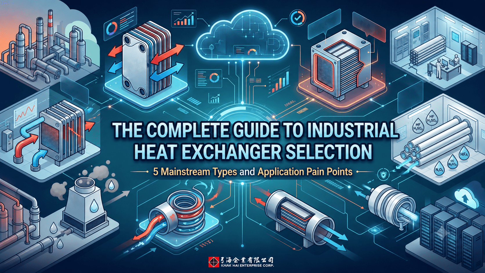
Whether in industrial manufacturing, semiconductor fabs, data centers, or Volatile Organic Compounds (VOCs) abatement systems, heat exchangers play a critical role in temperature regulation. However, faced with a dazzling array of specifications on the market, engineers and procurement personnel often encounter selection dilemmas: "Which one should be used for high temperature and high pressure?", "Will fluids containing particles cause clogging?", "Can it withstand strong acid and alkali processes?"
This article compiles the 5 most common types of industrial heat exchangers to help you quickly master the core principles of equipment selection.
What to Look for When Choosing a Heat Exchanger?
With so many types of industrial heat exchangers available, what are the most basic evaluation metrics for selection?
A: When selecting a heat exchanger, you cannot look at the price alone. Priority must be given to evaluating the following four process parameters:
- Fluid Characteristics: Is it corrosive? Does it contain solid particles, high viscosity, or is it prone to fouling/scaling?
- Operating Conditions: What are the maximum operating pressure and operating temperature?
- Allowable Pressure Drop: How much fluid resistance can the system withstand? This directly affects the energy consumption of the pumps.
- Maintenance Space: Is there enough space on-site for regular disassembly, cleaning, gasket replacement, or servicing?

In-Depth Analysis of 5 Mainstream Heat Exchangers
Q1: What is a "Plate Heat Exchanger"? What are its main advantages, limitations, and application scenarios?
- Advantages: The Plate Heat Exchanger (PHE) is currently a mainstream choice featuring extremely high heat transfer efficiency. Constructed from a series of corrugated metal plates, its structure is highly compact (space-saving), and its processing capacity can be flexibly adjusted by adding or reducing the number of plates.
- Pain Points & Limitations: Because the spacing between plates is narrow, clogging can easily occur if the fluid contains large particles or fibers. Furthermore, its pressure and temperature limits are constrained by the material of the rubber gaskets (commonly NBR, EPDM, Viton).
- Best Applications: Data center liquid cooling systems, general cooling water (RCW) systems, and HVAC systems.
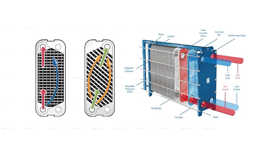
Schematic diagram of plate heat exchanger (gasketed / semi-welded)
Q2: How does a "Shell & Plate Heat Exchanger" differ from traditional shell-and-tube or plate types?
- Advantages: The Shell & Plate Heat Exchanger combines the benefits of both designs. The interior consists of a fully welded plate pack (yielding the high heat transfer efficiency of a plate type), while the exterior is enclosed by a round shell (yielding the high-temperature and high-pressure resistance of a shell-and-tube type).
- Common Selection Considerations: When planning production lines, many plant engineers consider market-common square all-welded block heat exchangers but often hesitate due to high initial procurement costs and long lead times for precision machining. In such cases, the shell & plate heat exchanger serves as an excellent alternative. It offers the same high heat-exchange efficiency of a gasket-free fully welded design, and its round shell provides superior structural stability when enduring extreme high pressures, delivering the best price-performance ratio for your project.
- Pain Points & Limitations: Since the internal plate pack features a fully welded design, if severe scaling occurs, it cannot be disassembled for plate-by-plate manual scrubbing like conventional plate types; it typically relies on Clean-in-Place (CIP) chemical cleaning.
- Best Applications: High-pressure refrigeration systems, high-temperature heavy chemical processes, and district energy systems.
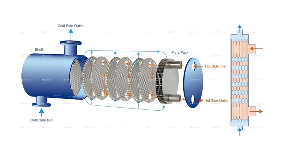
Schematic diagram of shell and plate heat exchanger
Q3: Why is a "Spiral Heat Exchanger" highly recommended for high-viscosity or fouling-prone wastewater?
- Advantages: The Spiral Heat Exchanger features a single-channel spiral configuration where fluid flows like navigating a maze. It possesses a powerful "Self-Cleaning Effect"—when a local channel narrows due to fouling, the flow velocity at that spot automatically accelerates. The resulting shear force flushes the dirt away, making it exceptionally resistant to clogging.
- Pain Points & Limitations: The physical footprint is usually quite large, and the initial cost for a single unit is higher than that of conventional equipment. However, it significantly reduces maintenance costs related to downtime for sludge cleaning.
- Best Applications: High-concentration fluids in chemical plants, sludge heat exchange, and process wastewater containing solid particles.
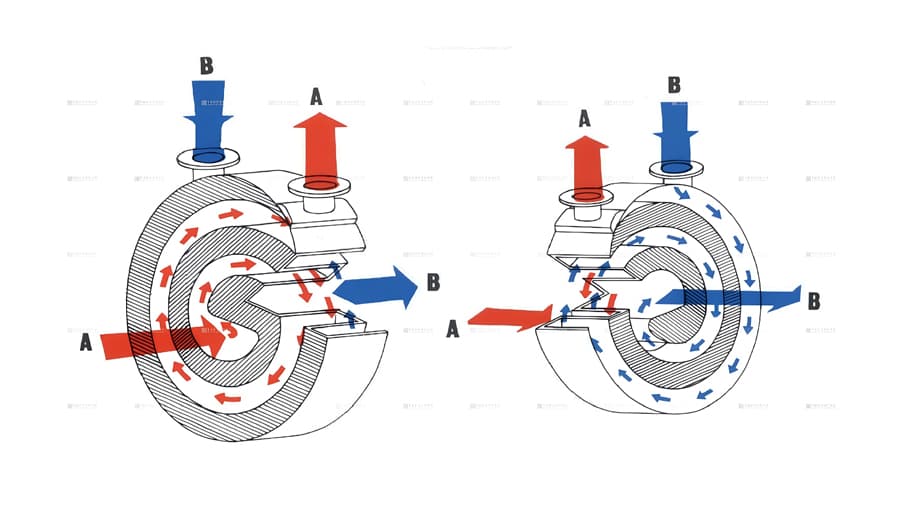
Schematic diagram of spiral heat exchanger
Q4: Why must "PTFE (Teflon) Heat Exchangers" be specified for strong acid and alkali processes in semiconductor fabs?
- Advantages: PTFE heat exchangers utilize high-grade polytetrafluoroethylene (Teflon) material, which provides near-perfect, extreme corrosion resistance capable of withstanding attacks from mixed acids (such as hydrofluoric acid and sulfuric acid) or strong alkalis. Crucially, it does not release any metal ions, meeting the strict "metal-free" high-purity requirements to prevent fluid contamination.
- Pain Points & Limitations: The thermal conductivity of plastic materials is significantly lower than that of metals. Therefore, heat exchange efficiency must be compensated for through highly optimized tube bundle designs and wall thickness controls. Additionally, its operating temperature and pressure cannot reach the levels of metal equipment.
- Best Applications: Semiconductor Ultra-Pure Water (UPW) systems, wafer cleaning processes, and electroplating solution heating/cooling.
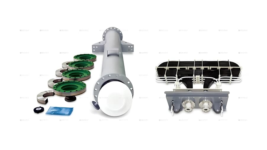
Schematic diagram of PTFE (Teflon) heat exchanger
Q5: What role does the "VOCs Gas-to-Liquid Heat Exchanger" play under trends of air pollution control and green energy conservation?
- Advantages: VOCs gas-to-liquid heat exchangers are primarily used in Volatile Organic Compounds (VOCs) condensation and recovery systems. They efficiently exchange heat between high-temperature organic exhaust gas and a liquid refrigerant, condensing the solvents in the exhaust gas into liquid form for recovery. This helps factories comply with environmental emission standards while recovering valuable solvents.
- Pain Points & Limitations: The heat transfer coefficient on the gas side is relatively low. During design, gas flow velocity and system pressure drop must be precisely balanced to avoid placing an excessive load on the downstream exhaust fan (RTO/rotor systems).
- Best Applications: VOCs exhaust gas treatment and solvent recovery in coating plants, printing plants, and petrochemical facilities.
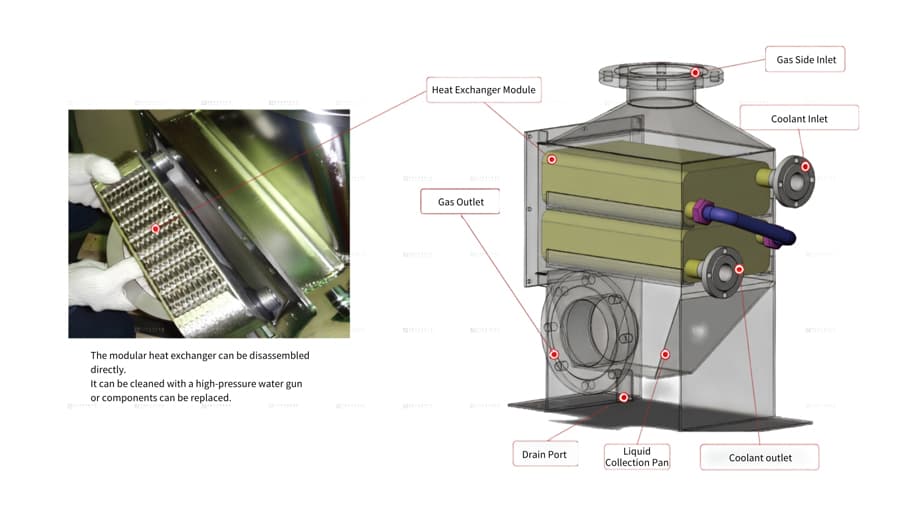
Schematic diagram of VOCs gas-to-liquid heat exchanger
Expert Recommendations from Gung Hai Enterprise
Heat exchanger selection is a specialized discipline that combines thermodynamics and materials science. If you currently have plant construction plans, equipment replacements, or are encountering troubleshooting issues such as abnormal pressure drop increases or drops in heat exchange efficiency, feel free to contact our technical team. We will provide tailored simulation calculations and selection planning for you.
Explore the Gung Hai Enterprise Heat Exchanger Product Line:
- Plate Heat Exchanger (Gasket Type & Semi-Welded Type): The industry mainstream featuring a compact structure and flexible capacity adjustment.
- Spiral Heat Exchanger: The anti-clogging champion specifically engineered for high-viscosity, fouling-prone, and particle-laden fluids.
- PTFE Heat Exchanger: The exclusive choice for semiconductor high-purity processes and strong acid/alkali environments requiring zero metal contamination.
- Gas-to-Liquid / Gas-to-Gas Heat Exchanger: Assisting enterprises in meeting environmental regulations through the highly efficient recovery of volatile organic compound solvents.
